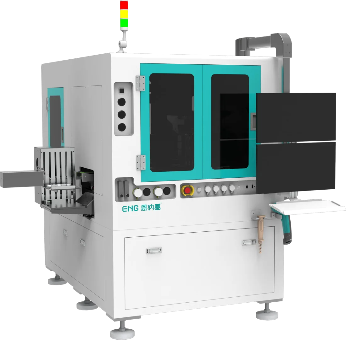
Gold-tin eutectic solder is the default die attach for high-power laser die, RF devices and hermetic builds. It is fluxless, it conducts heat well, and once it freezes nothing below 280 °C will re-melt it. The difficulty is not the alloy. It is holding a narrow thermal window on every bond while the die lands within a few microns of its optical position. This guide collects what published process notes say about that window, then maps each parameter to the machine capability that controls it.
Why 80Au/20Sn for laser and photonic die
The 80Au/20Sn composition is the eutectic point of the gold-tin system: it goes from solid to liquid at a single temperature, 280 °C, instead of over a melting range [1]. Supplier data lists a thermal conductivity of 0.57 W/cm·°C and a tensile and shear strength of 40,000 psi (275 MPa) [1]. Two properties matter most on a laser line:
- Heat path. The joint is both the electrical contact and the main heat path from the die to the submount. A weak thermal interface raises junction temperature, and laser output and lifetime fall with it [4].
- Step soldering. Because the joint does not re-melt until 280 °C, later lid sealing or board-level reflow will not float the die.
Gold-based solders also resist oxidation, which is why most eutectic laser diode attach uses hard AuSn rather than soft solders [4].
The key numbers at a glance
| Parameter | Published guidance | Why it matters | EX20 capability |
|---|---|---|---|
| Eutectic point | 80Au/20Sn melts at 280 °C [1] | Sets the floor of the profile and the step-soldering ladder | RT to 450 ℃ heating range |
| Peak at the joint | 330 to 350 °C typical with forming gas [2]; one laser maker caps at 340 °C [3] | Too low leaves oxide and poor wetting; too high grows intermetallics and stresses facets | ±5 ℃ temperature control |
| Time at peak | No more than 30 s with steady-state heat; 5 to 10 s at 340 °C with pulse heat [3] | Gold keeps dissolving into the joint while it is molten | Multi-stage profile, time set per stage |
| Ramp rate | Low-mass ceramic carriers can ramp faster than 50 °C/s with pulse heat [4] | Short cycles limit Sn oxidation and raise throughput | Controllable ramp, max >100 ℃/s |
| Atmosphere | N₂ against re-oxidation; N₂/H₂ forming gas, often 5 to 10% H₂, to reduce oxide [2] | AuSn is processed fluxless, so the gas does the work of a flux | Confirm gas setup in the sample evaluation |
| Preform footprint | About 90% of the die metallization [3][4]; 6 to 10 μm thick worked with large preform-to-die ratios [3] | AuSn wets in place and does not spread, so thickness variation stays in the joint [2] | Dipping head and dipping plate included |
| Bond force | Brittle InP and GaAs die limit how hard you can scrub [4] | Cracks and facet damage show up later as reliability failures | Voice coil, 20 to 50 g ±2 g or 50 to 300 g ±10% |
| Placement | Die can shift or swim while the joint is still liquid [4] | Optical alignment downstream depends on where the die freezes | ±1.5 μm @3σ XY, ±0.2° @3σ angle |
Bracketed numbers refer to the Sources list at the end. Published values are starting points from material suppliers and device makers, not a recipe for your parts. EX20 values are manufacturer data, H1 2026.
Peak temperature and time above liquidus
Because AuSn is eutectic, it needs little superheat to wet, but the surfaces it wets are rarely pure gold. A flash gold layer under 0.5 μm dissolves into the molten solder quickly, so the real joint forms with the nickel underneath, and nickel oxidizes [2]. That is why production peaks sit well above 280 °C: with forming gas, AuSn processes typically run at 330 to 350 °C for good oxide reduction [2].
The upper bound comes from the device. One laser chip maker's assembly note sets a maximum peak of 340 °C, holds the die at peak for no more than 30 seconds with steady-state heat, and found 5 to 10 seconds at 340 °C sufficient with pulse heat [3]. Gold keeps diffusing into the joint while it is molten, shifting the composition and growing intermetallics, so time above liquidus is a parameter you control, not a side effect.
On the machine, this means two things: temperature accuracy at the bond site, and a profile you can program stage by stage. The EX20 eutectic die bonder controls temperature to ±5 ℃ across RT to 450 ℃ and sets time, nozzle pressure, ramp rate and temperature independently for each profile stage.
Steady-state heat or pulse heat
There are two common ways to heat the joint [4]:
- Steady-state heat with scrub. The stage sits at a constant temperature and the tool moves the die in a small linear or orbital pattern to help wetting and push out voids. It is fast and simple, but it mechanically agitates the die, and brittle InP and GaAs die tolerate little of it.
- Pulse heat profiling. The temperature follows a programmed time profile under closed-loop control. It is gentler on III-V die. On low-mass ceramic carriers the ramp can exceed 50 °C per second, which keeps cycle times short.
For pulse heating, one laser maker suggests a background temperature of about 200 °C with the ramp to peak as fast as possible, and keeping the preform molten for as short a time as possible before the die lands, to limit tin oxide [3]. EX20 ramps at more than 100 ℃/s and uses two heating stations that run alternately, so one cools while the other bonds.
Atmosphere and oxide control
AuSn is processed without liquid flux. Nitrogen protects the parts from re-oxidizing during the cycle, and adding hydrogen as forming gas reduces the oxide already present [2]. Conveyor and belt processes typically use 5 to 10% hydrogen; mixes below about 5% are non-flammable but reduce oxide too slowly to be practical [2]. Fluxless also means cleanliness is not optional: handling contamination on preforms or substrates shows up as non-wetting and voids [2]. Agree the gas setup and incoming-part cleaning before you judge a sample run.
Preform size, pre-deposited AuSn and dipping
A common rule of thumb is a preform of about 90% of the die length and width, or of the die metallization [3][4]. With large preform-to-die ratios, one laser maker found 6 to 10 μm thick preforms adequate; where solder overflow at the die edge is a concern, a smaller footprint with more thickness keeps the volume constant [3]. AuSn wets in place rather than spreading, so any thickness variation in the preform stays in the finished joint [2].
Solder can also be pre-deposited on the submount or the die back side, which removes preform handling but heats every pad on the carrier at once [4]. EX20 ships with a dipping head and dipping plate, and handles die from 0.2 to 5 mm and 70 μm thick upward, with 180° die flip.
Placement accuracy and die swim
A laser die that moves a few microns after placement costs coupling efficiency at the next step. While the joint is liquid, die can shift or swim. AuSn helps here: gold absorbed from the pads makes the mixture gold-rich and raises its liquidus, which limits post-placement shift, reported as no more than 5 to 10 μm in a scrub process [4]. For tighter optical positions you need the bond head to hold the die through the freeze.
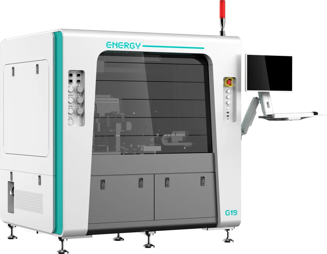
EX20 places to ±1.5 μm @3σ in XY and ±0.2° @3σ in angle, with voice-coil force control from 20 to 50 g at ±2 g for fragile die and 50 to 300 g at ±10% for larger parts. Where the process is epoxy or UV epoxy rather than eutectic, the G19 die bonder covers VCSEL, PD, TIA and COC placement at ±3 μm @3σ. Both appear in the optical module die bonding note.
Throughput: what the UPH figure includes
Eutectic UPH depends on the profile. EX20 is rated at 700 or more units per hour for single-die bonding excluding the profile time, with three pick-up heads, two eutectic heads and automatic nozzle change. A 10-second dwell at peak changes the real number, so ask for cycle time on your own profile, not a catalog figure.
What to send for a eutectic sample evaluation
- Die type, size, thickness and back-side metallization (for example EML, 0.3 × 0.8 mm, 100 μm).
- Submount or carrier material and its pad metallization stack.
- Solder format: preform size and thickness, or pre-deposited AuSn.
- Your current profile or the device maker's limits: peak, time at peak, atmosphere.
- Placement and angle targets, and how you inspect voids and shear.
With that, ENG engineers can run your parts on the eutectic die bonder and report placement accuracy and process notes before any quotation.
Sources
- [1] Indium Corporation, Eutectic Gold-Tin Solder product data sheet 97800 R5
- [2] Indium Corporation, Fluxless Soldering of 80Au/20Sn with Forming Gas/Inert Atmosphere (2017)
- [3] DenseLight, Handling and Mounting Chip on Submount, application note COS-APN001 Rev A
- [4] E. J. Wills, Die bonding for high-power devices, Advanced Packaging / Semiconductor Digest (2002)